

Introduction of What is an Op-Amp?
What is an Op-Amp? ~ Operational Amplifiers, commonly referred to as Op-Amps, are among the most widely used components in modern electronics. They play a vital role in signal processing, analog computations, instrumentation, and control systems. Whether you are a beginner in electronics or an experienced engineer, understanding the working principles, characteristics, and applications of op-amps is essential.
In this article, we will explore what an op-amp is, how it works, its internal structure, key parameters, and its real-world applications across industries.
What is an Op-Amp?
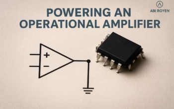
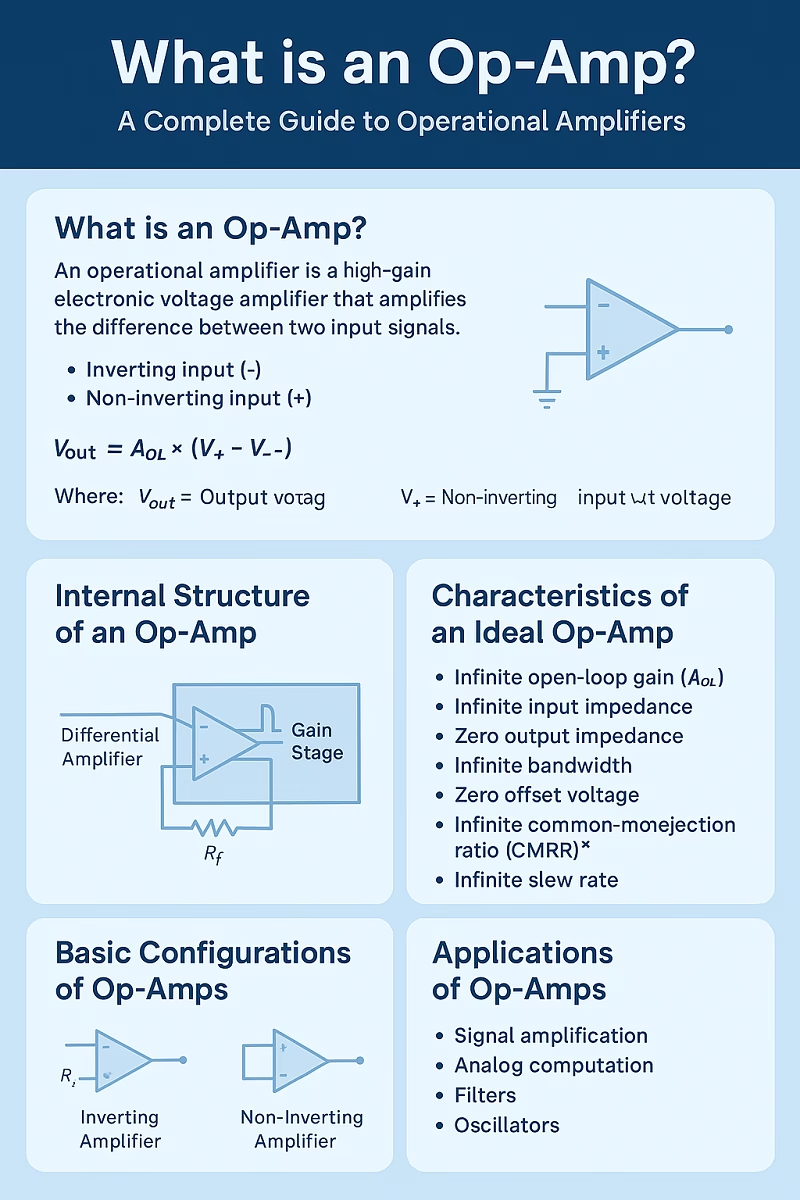
An Operational Amplifier (Op-Amp) is a high-gain electronic voltage amplifier that amplifies the difference between two input signals. It has two input terminals:
- Inverting input (-)
- Non-inverting input (+)
and one output terminal.
Mathematically, the output of an ideal op-amp is expressed as: Vout=AOL×(V+−V−)V_{out} = A_{OL} \times (V_{+} – V_{-})Vout=AOL×(V+−V−)
Where:
- VoutV_{out}Vout = Output voltage
- AOLA_{OL}AOL = Open-loop gain (very high in an ideal op-amp)
- V+V_{+}V+ = Non-inverting input voltage
- V−V_{-}V− = Inverting input voltage
Because of their high input impedance and low output impedance, op-amps can be used in countless analog circuits such as filters, amplifiers, oscillators, and integrators.
Internal Structure of an Op-Amp
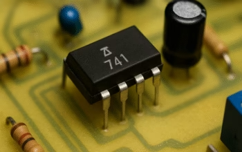
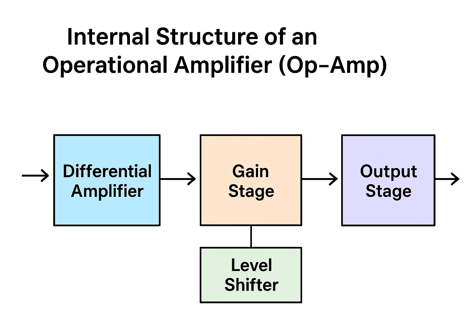
Although op-amps are available as integrated circuits (ICs), their internal design is based on a combination of fundamental electronic components:
- Differential Amplifier Stage
- The first stage that amplifies the difference between two input voltages.
- Provides high input impedance.
- Gain Stage
- A common-emitter amplifier stage that increases voltage gain.
- Level Shifting Stage
- Ensures correct DC biasing and shifts the signal level.
- Output Stage
- Provides low output impedance for driving loads effectively.
This structure enables op-amps to achieve very high gain and stable performance.
Characteristics of an Ideal Op-Amp
While practical op-amps have limitations, the ideal op-amp model helps in analysis and design. The characteristics of an ideal op-amp are:
- Infinite open-loop gain (AOLA_{OL}AOL)
- Infinite input impedance
- Zero output impedance
- Infinite bandwidth
- Zero offset voltage
- Infinite common-mode rejection ratio (CMRR)
- Infinite slew rate
In reality, no op-amp is ideal, but modern designs come close enough to meet engineering requirements.
Important Parameters of Op-Amps
When choosing an op-amp for practical applications, several key parameters must be considered:
- Input Offset Voltage – The voltage required to make the output zero.
- Input Bias Current – Small currents flowing into input terminals.
- Slew Rate – Maximum rate of change of output voltage (V/µs).
- Common-Mode Rejection Ratio (CMRR) – Ability to reject common-mode signals.
- Power Supply Rejection Ratio (PSRR) – Resistance to power supply variations.
- Gain Bandwidth Product (GBW) – Maximum frequency at which op-amp can provide unity gain.
These specifications determine how suitable an op-amp is for precision, speed, or power applications.
Basic Configurations of Op-Amps
Op-amps can be configured in several ways to achieve different functions:
1. Inverting Amplifier
- Input signal is applied to the inverting terminal.
- Produces an output signal 180° out of phase with input.
- Gain = −Rf/Rin-R_f / R_{in}−Rf/Rin.
2. Non-Inverting Amplifier
- Input signal is applied to the non-inverting terminal.
- Produces output in phase with input.
- Gain = 1+(Rf/Rin)1 + (R_f / R_{in})1+(Rf/Rin).
3. Voltage Follower (Buffer)
- Unity gain configuration.
- Provides high input impedance and low output impedance.
4. Summing Amplifier
- Adds multiple input signals together.
- Useful in audio mixing and signal combination.
5. Integrator and Differentiator
- Integrator: Produces output proportional to the integral of input signal.
- Differentiator: Produces output proportional to the derivative of input signal.

Applications of Op-Amps
Op-amps are found in nearly every analog electronic device. Some common applications include:
- Signal Amplification
- Audio amplifiers, sensor signal conditioning, and instrumentation amplifiers.
- Analog Computation
- Used in calculators, simulators, and control systems to perform addition, subtraction, integration, and differentiation.
- Filters
- Active filters (low-pass, high-pass, band-pass, notch filters) for audio and communication systems.
- Oscillators
- Generating waveforms such as sine, square, and triangle signals.
- Voltage Regulators & Power Supplies
- Used in linear regulators and precision voltage references.
- Control Systems
- Feedback loops in robotics, automation, and industrial processes.
- Analog-to-Digital & Digital-to-Analog Interfaces
- Signal conditioning before conversion.
Advantages of Using Op-Amps
- High gain with small input signal
- Compact IC packaging
- Versatile configurations
- Cost-effective and widely available
- Reliable performance in analog applications
Limitations of Op-Amps
Despite their wide usage, op-amps have some practical limitations:
- Limited bandwidth at high gain
- Non-zero input offset voltage
- Power consumption in high-speed models
- Limited slew rate for fast-changing signals
Conclusion of What is an Op-Amp?
An Operational Amplifier (Op-Amp) is a crucial building block in electronics. Its ability to amplify signals, perform mathematical operations, and drive loads makes it indispensable in audio systems, instrumentation, communication devices, and control systems.
By understanding the structure, characteristics, configurations, and applications of op-amps, engineers and hobbyists can design circuits more effectively.
In short, without op-amps, modern electronics as we know it today would not exist.