

A digital potentiometer (often called a digipot or digital variable resistor) is an electronic component used to adjust resistance values through digital control rather than manual turning of a knob or slider. It functions similarly to a traditional potentiometer but is operated electronically using signals from a microcontroller, digital circuit, or other programmable devices.
Digital potentio-meters have become an essential part of modern electronics because they offer high precision, repeatability, and easy integration with automated systems. From audio equipment to industrial controls, digipots are replacing mechanical potentiometers in many applications.
1. What is a Digital Potentiometer?
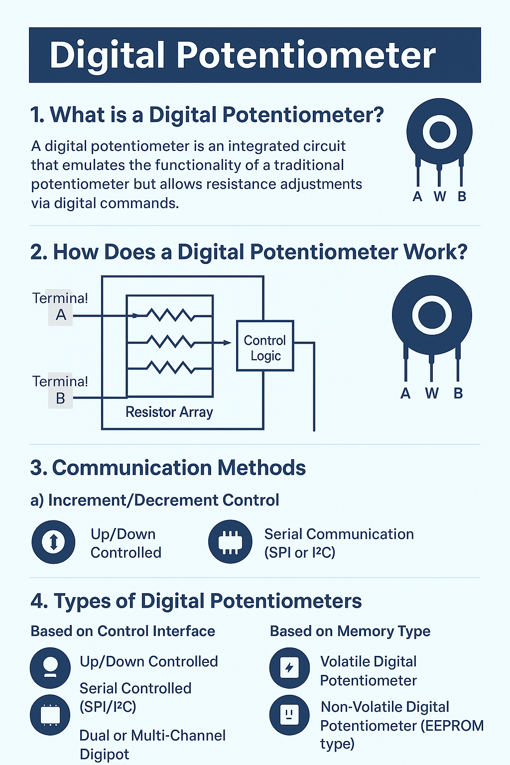
A digital potentiometer is an integrated circuit (IC) that emulates the functionality of a traditional potentiometer but allows resistance adjustments via digital commands. Instead of physically rotating a shaft to change resistance, the resistance is set electronically using digital inputs.
In most cases, the resistance value is adjusted through up/down control pins or a serial communication interface such as SPI (Serial Peripheral Interface) or I²C (Inter-Integrated Circuit).
2. How Does a Digital Potentiometer Work?
The core of a digital potentio-meter consists of:
- Resistor Array – A series of resistors connected in sequence inside the IC.
- Electronic Switches – MOSFET-based switches select the tap point along the resistor chain.
- Control Logic – A digital circuit that receives commands from the user or microcontroller.
When a digital command is given, the control logic changes the switch position, thereby selecting a different resistance value between the wiper and the fixed terminals.
Basic Terminals of a Digital Potentiometer:
- Terminal A (High End) – One end of the resistor chain.
- Terminal B (Low End) – The other end of the resistor chain.
- Wiper (W) – Adjustable tap point selected by the control circuit.
The resistance between these terminals changes depending on the wiper position, just like in a mechanical potentiometer.
3. Communication Methods
Digital potentiometers can be controlled in two main ways:
a) Increment/Decrement Control
Uses push buttons or control pins to step the resistance value up or down.
b) Serial Communication (SPI or I²C)
Allows precise adjustment by sending digital commands from a microcontroller, making it ideal for automated systems.
4. Types of Digital Potentiometers
There are several classifications of digital potentio-meters based on their features and construction:
a) Based on Control Interface:
- Up/Down Controlled – Simple control with increase/decrease commands.
- Serial Controlled (SPI/I²C) – Controlled by sending commands over serial communication lines.
b) Based on Number of Channels:
- Single-Channel Digipot – One adjustable resistor.
- Dual or Multi-Channel Digipot – Multiple adjustable resistors in one package.
c) Based on Memory Type:
- Volatile Digital Potentiometer – Loses resistance settings when power is turned off.
- Non-Volatile Digital Potentiometer (EEPROM type) – Retains settings after power loss.
5. Advantages of Digital Potentiometers
- No Mechanical Wear – No moving parts, ensuring long lifespan.
- High Precision – Fine resistance adjustments in small increments.
- Remote Control Capability – Can be adjusted by microcontrollers and digital circuits.
- Compact Size – Integrated in small IC packages.
- Automation-Friendly – Ideal for systems requiring frequent and automated adjustments.
6. Limitations of Digital Potentiometers
While highly useful, digital potentio-meters have some drawbacks:
- Lower Power Handling – Not suitable for high-current applications like large audio amplifiers.
- Limited Resistance Range – Commonly available in fixed ranges like 10 kΩ, 50 kΩ, or 100 kΩ.
- Resolution Limits – Resistance changes in discrete steps (e.g., 256 steps).
7. Applications of Digital Potentiometers
Digital potentiometers are used in various electronics applications where adjustable resistance is needed:
- Audio Volume Control – Adjusting sound levels in amplifiers without mechanical knobs.
- Sensor Calibration – Fine-tuning sensor output for accuracy.
- LCD Contrast Adjustment – Setting optimal display contrast in embedded systems.
- Industrial Automation – Precise control of process variables in machinery.
- Data Acquisition Systems – Calibrating signal levels before analog-to-digital conversion.
- Communication Devices – RF tuning and impedance matching.
8. Example: How to Use a Digital Potentiometer with Arduino
A popular digital potentio-meter IC is MCP41010 from Microchip, which uses the SPI protocol.
Basic Steps:
- Connect MCP41010 to Arduino (MOSI, MISO, SCK, and CS pins).
- Write an Arduino program to send SPI commands for setting the resistance.
- Observe changes in output voltage or current based on wiper position.
This setup allows automated, programmable resistance control in electronics projects.

9. Digital Potentiometer vs. Mechanical Potentiometer
| Feature | Digital Potentiometer | Mechanical Potentiometer |
|---|---|---|
| Control Method | Digital commands | Manual rotation/slider |
| Mechanical Wear | None | Yes |
| Automation Capability | Yes | No |
| Power Handling | Low | Medium to High |
| Retains Settings | Some models only | Always |
10. Choosing the Right Digital Potentiometer
When selecting a digital potentio-meter, consider:
- Resistance Value (e.g., 10 kΩ, 50 kΩ, 100 kΩ)
- Number of Steps / Resolution (e.g., 64, 128, 256 steps)
- Interface Type (SPI, I²C, Up/Down control)
- Voltage Range (Ensure compatibility with your circuit)
- Volatile or Non-Volatile Memory (If retention is required)
Conclusion
Digital potentiometers are revolutionizing the way engineers and hobbyists design adjustable circuits. By replacing manual control with precise digital adjustments, they improve accuracy, durability, and automation in electronic systems. Whether for audio, industrial, or embedded applications, digital potentiometers are an excellent choice for modern designs.
With the growing trend toward smart electronics and IoT devices, digital potentio-meters will continue to play a key role in optimizing and automating electronic control systems.