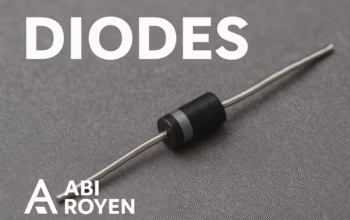


1. Introduction to Zener Diodes
A Zener diode is a special type of semiconductor diode that allows current to flow in the reverse direction when a specific voltage, known as the Zener voltage, is reached. Unlike regular diodes that block reverse current, Zener diodes are designed to operate reliably in the breakdown region without being damaged.
These diodes are widely used in voltage regulation, overvoltage protection, and reference voltage circuits, making them an essential component in modern electronics.
2. Working Principle of Zener Diodes
A Zener diode functions based on the principle of reverse bias breakdown. When the reverse voltage applied to the diode exceeds a certain limit (Zener voltage), the diode starts conducting in reverse.
2.1 Forward Bias Operation
In forward bias mode, the Zener diode behaves like a regular diode, allowing current to flow when the voltage exceeds the forward voltage (typically around 0.7V for silicon-based diodes).
2.2 Reverse Bias Operation
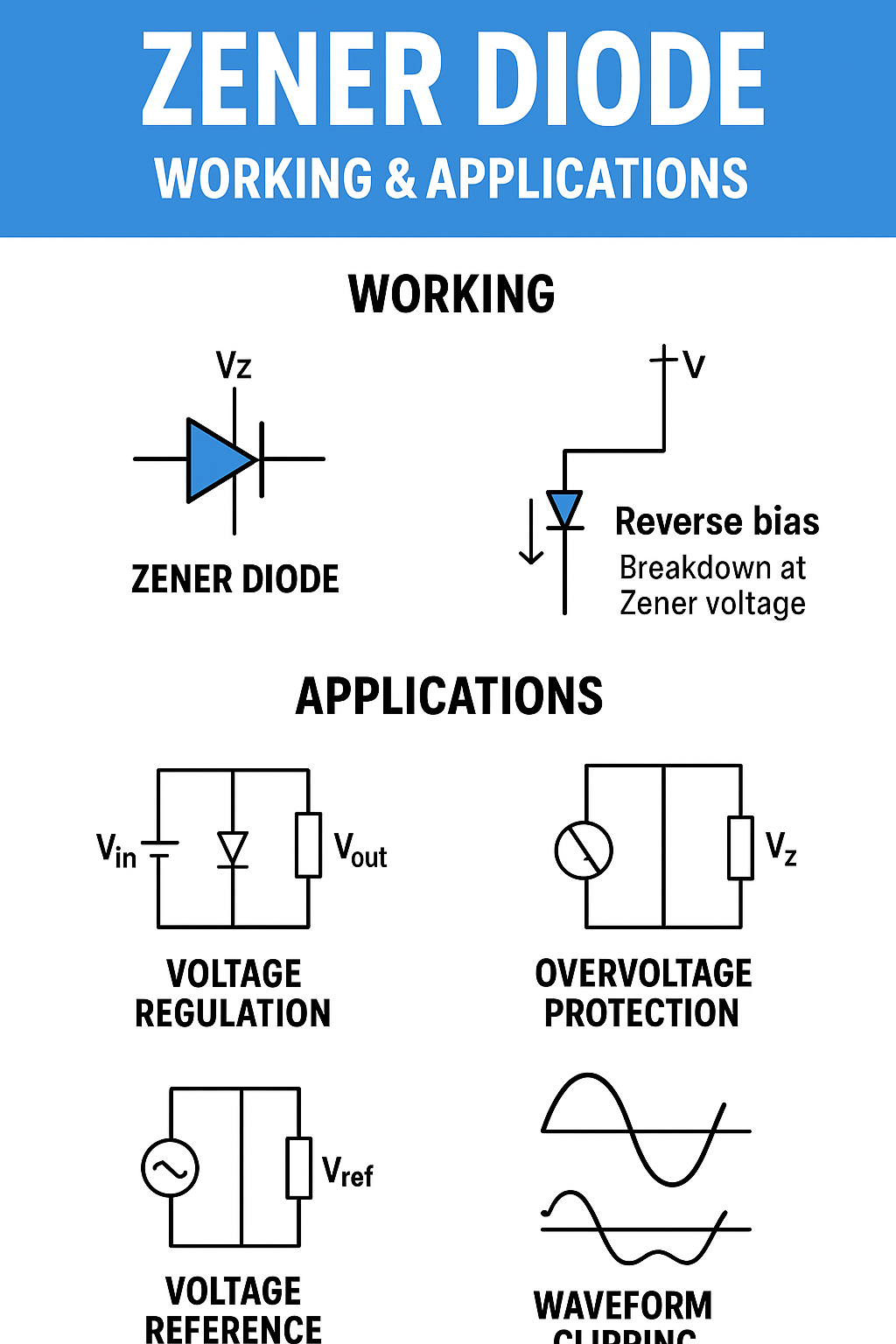
In reverse bias, the Zener diode initially blocks the current until the reverse voltage reaches the breakdown point (Zener voltage). At this point, the diode allows a significant reverse current to flow without damage, as long as the current remains within the diode’s specified limits.
3. Zener diodes Breakdown vs. Avalanche Breakdown
The reverse breakdown in diodes can occur due to two mechanisms:
- Zener Breakdown: Occurs at low breakdown voltages (typically below 5V) due to quantum tunneling of electrons.
- Avalanche Breakdown: Occurs at higher voltages, where electrons gain enough energy to knock out more electrons, creating a chain reaction.
In many Zener diodes, both mechanisms may occur depending on the voltage rating.
4. Characteristics of Zener Diodes
The key characteristics of Zener diodes include:
- Zener Voltage (Vz) – The breakdown voltage at which the diode starts conducting in reverse.
- Maximum Power Dissipation (Pmax) – The highest power the diode can handle without overheating.
- Reverse Current (Iz) – The current flowing through the diode in reverse breakdown mode.
- Voltage Tolerance – The accuracy of the Zener voltage, typically ±5% or better for precision diodes.
5. Zener Diodes Symbol and Circuit Representation
The symbol of a Zener diode is similar to that of a regular diode but with bent edges on the cathode line.
In circuit diagrams, the cathode is marked with a line, and the anode is the other terminal. The cathode is usually connected to the positive voltage in reverse bias regulation applications.
6. Applications of Zener Diodes
Zener diodes are extremely versatile in electronic circuits. Some of the most common applications include:
6.1 Voltage Regulation
Zener diodes are widely used as voltage regulators to maintain a constant output voltage, even when the input voltage or load changes.
Example: In a 5V regulated power supply, a 5.1V Zener diode can be connected across the load to stabilize voltage.
6.2 Overvoltage Protection
Zener diodes protect sensitive electronic components from voltage spikes by clamping the voltage to a safe level.
6.3 Voltage Reference in Circuits
Zener diodes provide a stable reference voltage for analog-to-digital converters, oscillators, and precision measurement devices.
6.4 Waveform Clipping and Shaping
In signal processing, Zener diodes can clip waveforms to prevent signal peaks from exceeding a desired level.
6.5 Switching Operations
In some cases, Zener diodes are used in switching circuits to control transistor biasing.

7. Zener Diodes as a Voltage Regulator – Example Circuit
Simple Voltage Regulator Circuit:
- Components: Zener diode, resistor, power supply, load.
- Working: The resistor limits the current to the Zener diode, ensuring it operates within safe limits. The Zener diode clamps the voltage across the load to its rated breakdown voltage.
Formula for Resistor Value: R=Vin−VzIz+ILR = \frac{V_{in} – V_z}{I_z + I_L}R=Iz+ILVin−Vz
Where:
- VinV_{in}Vin = Input voltage
- VzV_zVz = Zener voltage
- IzI_zIz = Zener current
- ILI_LIL = Load current
8. Choosing the Right Zener Diodes
When selecting a Zener diode for your project, consider:
- Zener Voltage – Choose based on the required regulated voltage.
- Power Rating – Ensure it can handle the expected load.
- Tolerance – For precision applications, use a diode with a low tolerance percentage.
- Package Type – Choose through-hole or SMD based on circuit design.
9. Advantages of Zener Diodes
- Simple and cost-effective voltage regulation.
- Reliable operation in breakdown mode.
- Wide range of voltage ratings available.
- Compact size suitable for small circuits.
10. Limitations of Zener Diodes
- Limited to low power regulation.
- Poor efficiency for large voltage drops.
- Requires a resistor for current limiting.
- Generates heat in high current applications.
11. Conclusion
Zener diodes are fundamental components in electronics, offering a simple and reliable method for voltage regulation, overvoltage protection, and reference voltage generation. Understanding their working principles, characteristics, and limitations is crucial for designing efficient and stable electronic circuits.
Whether used in a small hobby project or a complex industrial system, Zener diodes continue to play a vital role in ensuring stable and safe operation of electronic devices.