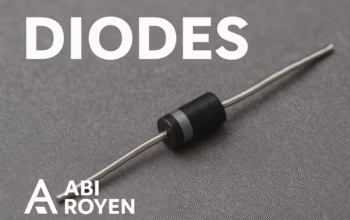


In modern electronics, the ability to control circuit parameters precisely is essential, especially in applications like radio frequency (RF) tuning, voltage-controlled oscillators (VCOs), and frequency modulation. One component that plays a significant role in these systems is the Varactor Diode, also known as the Varicap Diode or Voltage-Controlled Capacitor.
This article explores what varactor diodes are, how they work, their characteristics, and the many applications where they are used.
What is a Varactor Diode?
A Varactor Diode is a semiconductor device that behaves like a variable capacitor when reverse-biased. The term “varactor” comes from “variable reactance.” Unlike regular diodes that are designed for current rectification, varactor-diodes are designed specifically to exploit the voltage-dependent capacitance of the p-n junction.
Varactor-diodes are widely used in RF circuits because their capacitance changes in response to the applied reverse voltage, allowing precise tuning of frequency.
Working Principle of Varactor Diode
The working of a varactor diode relies on the capacitance variation of a reverse-biased p-n junction.
When a diode is reverse-biased:
- No current flows (ideally) through the junction, except for a small leakage.
- The depletion region at the junction widens as the reverse voltage increases.
- This widening reduces the capacitance, because the depletion region acts like a dielectric between two plates.
The capacitance CCC of the diode can be approximated by the equation: C=εAdC = \frac{\varepsilon A}{d}C=dεA
Where:
- ε\varepsilonε = permittivity of the material
- AAA = area of the junction
- ddd = width of the depletion layer
As the reverse bias voltage increases, ddd increases, which reduces the capacitance. This is the key property that makes varactor-diodes useful for tuning purposes.
Symbol and Construction Varactor Diode
- Symbol: The symbol of a varactor-diode is similar to a normal diode but includes parallel lines representing a capacitor.
- Construction: Varactor-diodes are made from silicon and designed to have a controlled junction capacitance. They are encapsulated in standard diode packages for protection.
Key Characteristics of Varactor Diode
When selecting a varactor diode, the following characteristics are important:
- Capacitance Range
- Defined between a minimum and maximum reverse bias voltage.
- Typical range: 1 pF to 500 pF.
- Quality Factor (Q-Factor)
- Higher Q-factor means lower energy loss at high frequencies.
- Reverse Breakdown Voltage
- Maximum reverse voltage before the diode conducts significantly.
- Series Resistance
- Lower series resistance improves performance in RF circuits.
- Temperature Coefficient
- Stability of capacitance over temperature variations.
Advantages of Varactor Diode
- Compact and reliable
- Low cost compared to mechanical tuning devices
- No moving parts, hence longer lifespan
- Easy to integrate into electronic tuning circuits
- Wide capacitance variation range
Disadvantages of Varactor Diode
- Limited to low power applications
- Sensitive to temperature changes
- Capacitance range may be smaller compared to mechanical tuners
Applications of Varactor Diode
Varactor-diodes are essential in various electronic systems, especially in RF and microwave applications. Some of the most common uses include:
1. Tuning Circuits
Used in FM radios, television tuners, and communication receivers to adjust the resonance frequency electronically without moving parts.
2. Voltage-Controlled Oscillators (VCOs)
In RF transmitters and synthesizers, VCOs use varactor diodes to adjust the output frequency based on a control voltage.
3. Frequency Modulation (FM)
By varying the reverse bias voltage, the capacitance changes and hence modulates the carrier frequency.
4. Phase-Locked Loops (PLLs)
Varactors help fine-tune the oscillator frequency to maintain synchronization in communication systems.
5. Frequency Multipliers
Used in frequency multiplier circuits to generate harmonics of an input signal.
6. RF Filters
Capacitance adjustment allows dynamic tuning of RF filter response for better signal quality.
Example Circuit: Varactor Diode in a Tuning Circuit
A simple LC circuit can be tuned electronically by replacing the capacitor with a varactor-diode in reverse bias. By applying a variable DC control voltage, the resonant frequency changes, making it ideal for automatic frequency control.
Selection Tips for Varactor Diodes
When choosing a varactor-diode for your application, consider:
- Required frequency range
- Capacitance variation range
- Q-factor for your operating frequency
- Power handling capability
- Temperature stability requirements


Future Trends of Varactor Diodes
With the advancement of 5G networks, satellite communication, and IoT devices, the demand for high-performance tuning components like varactor diodes will continue to grow. Modern designs are focusing on:
- Lower parasitic resistance
- Higher Q-factor for better RF efficiency
- Integration into monolithic microwave integrated circuits (MMICs)
Conclusion
The varactor diode is a small yet powerful component in modern electronics. Its ability to vary capacitance with applied voltage makes it indispensable in RF tuning, VCOs, PLLs, and various frequency control applications.
By understanding its working principle, characteristics, and limitations, engineers can design more efficient and reliable electronic systems.
✅ For more electronics component guides, visit: Abi Royen Electronics Blog