

Ferrite beads are essential components in electronic circuits, especially for controlling electromagnetic interference (EMI) and radio frequency interference (RFI). These passive devices are designed to suppress high-frequency noise in power lines and signal lines. While widely used, ferrite beads are often misunderstood or assumed to function properly without verification. In reality, testing ferrite beads is crucial to ensure their performance in a circuit.
This article explores why testing ferrite beads is important, outlines several methods used for testing, and provides practical best practices for engineers and technicians.
What Are Ferrite Beads?
A ferrite bead (or ferrite choke) is a passive electronic component made from a ferrite material, typically shaped as a small cylinder or surface-mount block. It acts as a low-pass filter, allowing DC and low-frequency signals to pass while attenuating high-frequency noise.
Ferrite beads operate by converting unwanted high-frequency energy into heat through their magnetic resistance (impedance). They are commonly found in:
- Power supply lines
- USB data lines
- Audio and video circuits
- RF circuits
Why Test Ferrite Beads?
Although ferrite beads are generally reliable, several factors make testing important:
- Component Quality Variations: Different manufacturers may produce beads with slight variances.
- Failure in Harsh Conditions: High temperature or current overload can degrade the bead’s performance.
- Incorrect Installation: In SMD components, improper soldering can affect function.
- Aging and Wear: Over time, ferrite materials can deteriorate, especially in high-stress environments.
- Design Validation: Testing confirms that the selected bead meets circuit requirements.
By testing ferrite beads, engineers can ensure signal integrity, reduce EMI risks, and improve product reliability.
Common Methods to Test Ferrite Beads
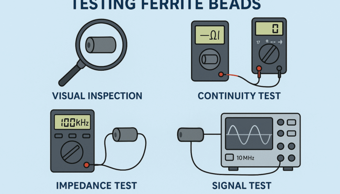
1. Visual Inspection
Purpose: To detect physical damage, cracks, or manufacturing defects.
Tools Needed:
- Magnifying glass or microscope
Checklist:
- Look for cracks or chipping
- Check solder joints (for SMD)
- Ensure the bead is not loose or burned
While basic, visual inspection can often catch manufacturing or installation defects early.
2. Continuity Testing Ferrite Beads with a Multimeter
Purpose: To check if the ferrite bead is internally broken (open circuit).
Tools Needed:
- Digital multimeter with continuity test mode
Steps:
- Disconnect the ferrite bead from the circuit or isolate it.
- Set the multimeter to continuity mode.
- Place probes across the bead terminals.
- A “beep” or near-zero resistance (typically <1Ω) means continuity is present.
Note: This test doesn’t reveal frequency filtering performance but ensures the bead is not open.
3. Resistance Testing
Purpose: To ensure that the bead’s DC resistance (DCR) is within specifications.
Tools Needed:
- Precision ohmmeter or LCR meter
Steps:
- Measure resistance across terminals.
- Compare with datasheet DCR values.
Most ferrite beads have a very low DC resistance (typically <1Ω). If resistance is much higher, the component may be damaged.
4. Impedance Testing (Using an LCR Meter or Impedance Analyzer)
Purpose: To measure the actual impedance over a frequency range.
Tools Needed:
- LCR meter or impedance analyzer
Steps:
- Connect the bead to the meter or analyzer.
- Measure impedance at various frequencies (e.g., 100 kHz, 10 MHz, 100 MHz).
- Compare with manufacturer’s impedance vs. frequency chart.
This is the most accurate method to verify if the bead is filtering the desired frequency range correctly.
5. Circuit Testing Ferrite Beads with Oscilloscope and Signal Generator
Purpose: To simulate real-world performance and observe signal noise suppression.
Tools Needed:
- Oscilloscope
- Signal generator
- Test PCB or breadboard
Steps:
- Insert the ferrite bead into a test circuit.
- Inject a noisy or high-frequency signal.
- Monitor the output across the bead using the oscilloscope.
- Compare signals with and without the bead.
This method shows practical effectiveness in a working circuit.

Best Practices for Testing Ferrite Beads
- Know Your Specs: Always refer to the datasheet before testing.
- Use Proper Tools: An LCR meter with frequency sweep capability is ideal.
- Test in Isolation: If possible, test ferrite beads outside the circuit for accurate readings.
- Document Results: Record impedance values at multiple frequencies.
- Compare Brands: Test samples from different manufacturers during design stages.
- Include Tolerance Margins: Select beads with impedance values comfortably above the required filtering threshold.
How to Testing Ferrite Beads SMD on PCB
SMD ferrite beads are commonly used in compact electronics. Testing these on a PCB can be done using:
- Probe test points: If the PCB has exposed pads before and after the bead.
- Back-probing: Use oscilloscope probes to check signal suppression in real time.
- In-circuit impedance test: Only if the circuit allows isolation of the bead.
Warning: In-circuit testing may be affected by other components and parasitics.
Common Issues and Troubleshooting
| Issue | Possible Cause | Solution |
|---|---|---|
| No continuity | Open bead | Replace the component |
| High resistance | Damaged or overheated bead | Test new bead |
| No filtering effect | Wrong impedance value or frequency range | Re-evaluate bead selection |
| Signal degradation | Bead affects low-frequency signal | Choose a bead with suitable cutoff |
When to Replace a Ferrite Bead
You should consider replacing a ferrite bead if:
- It fails continuity/resistance testing
- Shows signs of overheating or cracking
- Is not performing as expected in signal suppression
- Has been subjected to transient overcurrent or ESD
Conclusion about Testing Ferrite Beads
Testing ferrite beads is a crucial step in ensuring the reliability and performance of electronic systems. From simple continuity checks to advanced impedance testing, each method plays a role in identifying faulty components and validating circuit design.
Whether you are a hobbyist, technician, or professional engineer, understanding how to test ferrite beads will improve the quality of your electronic designs, reduce EMI problems, and enhance overall product performance.
About Abi Royen
At Abi Royen, we aim to provide high-quality insights into electronic components, testing methods, and industry standards. Visit our blog for more in-depth guides and technical resources.