

Introduction of Structure of a Thyristor
Structure of a Thyristor ~ In the field of power electronics, the thyristor is one of the most important semiconductor devices used for controlling high voltage and high current applications. Known for its efficiency and ability to switch electrical power with precision, the thyristor plays a critical role in modern power systems.
To understand its functionality, it is crucial to analyze its internal structure. The structure of a thyristor directly determines how it conducts, blocks, and controls current flow in a circuit. In this article, we will explore the detailed construction, layers, junctions, and working principle of a thyristor, along with its real-world applications.
What is a Thyristor?
A thyristor is a solid-state semiconductor device that acts as a switch, controlling the flow of electrical power. It is primarily used in high-voltage and high-current applications such as motor drives, power supplies, and inverter circuits.
The most common type of thyristor is the Silicon Controlled Rectifier (SCR), which consists of four semiconductor layers and three junctions. By design, a thyristor can remain in the conducting state until the current falls below a certain level or until external control is applied.
Basic Structure of a Thyristor
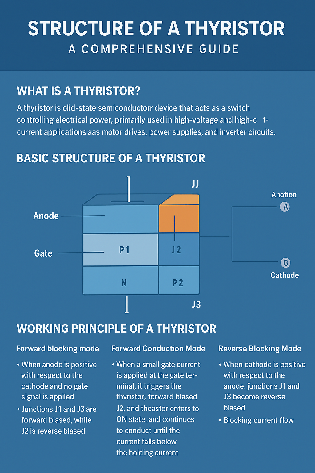
The thyristor structure is what makes it unique compared to other semiconductor devices. It consists of:
- Four Layers of Semiconductors (PNPN)
- Alternating layers of P-type and N-type semiconductor materials.
- These layers are arranged in the order P1 – N1 – P2 – N2.
- Three Junctions (J1, J2, J3)
- Junctions are formed where the P-type and N-type materials meet.
- J1 is between P1 and N1, J2 is between N1 and P2, and J3 is between P2 and N2.
- Three Terminals
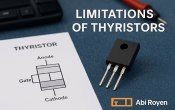
- Anode (A): Connected to the outer P-layer (P1).
- Cathode (K): Connected to the outer N-layer (N2).
- Gate (G): Connected to the inner P-layer (P2), which controls switching.
This layered design makes the thyristor function like a combination of two transistors connected in a feedback loop.
Detailed Layer Explanation
1. P1 Layer (Anode Region)
- Heavily doped P-type material.
- Connected directly to the anode terminal.
- Responsible for injecting holes during conduction.
2. N1 Layer
- Lightly doped N-type region with a large width.
- Acts as the voltage-blocking layer, sustaining high reverse voltages.
3. P2 Layer (Gate Region)
- Moderately doped P-type material.
- Connected to the gate terminal, which triggers the thyristor into conduction.
4. N2 Layer (Cathode Region)
- Heavily doped N-type material.
- Connected directly to the cathode terminal.
- Provides electron injection during conduction.
Working Principle of a Thyristor
The working of a thyristor is based on the interaction between its three junctions (J1, J2, J3):
- Forward Blocking Mode
- When the anode is positive with respect to the cathode but no gate signal is applied.
- Junctions J1 and J3 are forward biased, while J2 is reverse biased.
- Only a small leakage current flows, keeping the thyristor in the OFF state.
- Forward Conduction Mode
- When a small gate current is applied at the gate terminal, it triggers the thyristor.
- This forward biases J2, allowing large current to flow from anode to cathode.
- The thyristor enters the ON state and continues to conduct until current falls below the holding current.
- Reverse Blocking Mode
- When the cathode is positive with respect to the anode.
- Junctions J1 and J3 become reverse biased.
- The thyristor blocks current flow in this condition.
Equivalent Circuit of a Thyristor
The internal structure of a thyristor can also be represented as a two-transistor model:
- Transistor T1 (PNP type)
- Transistor T2 (NPN type)
These two transistors are connected in such a way that the output of one drives the input of the other. This regenerative feedback loop explains how a small gate current can trigger a large anode-to-cathode current.
Key Features of Structure of a Thyristor
- Four-layer, three-junction design enables high current control.
- Gate control mechanism allows external switching.
- Latch-up behavior ensures the device stays ON once triggered.
- High power handling capability due to the thick N1 layer.
Applications of Thyristors
Because of their efficient structure, thyristors are used in numerous industrial and consumer applications, including:
- Motor Speed Control – In DC and AC motor drives.
- Power Supplies – As controlled rectifiers and inverters.
- Light Dimmers – For controlling the brightness of lamps.
- Overvoltage Protection – As crowbar circuits.
- HVDC Transmission Systems – For efficient long-distance power transmission.

Advantages of Structure of a Thyristor
- High voltage and current rating.
- Compact design compared to mechanical switches.
- High efficiency with minimal power loss.
- Ability to control large amounts of power using a small gate signal.
Limitations of Thyristors
Despite their advantages, thyristors also have limitations due to their structure:
- Cannot be turned off using the gate (needs current interruption).
- Limited switching speed compared to modern semiconductor devices like IGBTs.
- Require proper cooling in high-power applications.
Conclusion of Structure of a Thyristor
The structure of a thyristor—consisting of four semiconductor layers, three junctions, and three terminals—forms the foundation of its operation in power electronics. By understanding its internal design, engineers and students can better appreciate its function in controlling electrical power efficiently.
With applications ranging from motor control to power transmission, the thyristor remains a cornerstone device in modern electronics. Despite competition from newer semiconductor technologies, its simple yet powerful structure ensures it will continue to be widely used in many industries.