

Introduction
Structure metal film resistor ~ In modern electronics, resistors play a fundamental role in controlling current and voltage within circuits. Among the many types of resistors available, metal film resistors stand out due to their accuracy, stability, and reliability. These characteristics are largely attributed to their unique structure and manufacturing process.
This article will explore the structure of metal film resistors in depth, covering the materials used, construction techniques, protective coatings, and the advantages that come from this specific build. By understanding the internal structure, engineers and enthusiasts can better select and utilize metal film resistors in a wide range of electronic applications.
What is a Metal Film Resistor?
A metal film resistor is a type of fixed resistor made by depositing a thin layer of metal onto a ceramic substrate. It is primarily used in electronic circuits where precision and low tolerance are critical. These resistors are known for their excellent temperature stability, low noise, and high accuracy compared to carbon-based resistors.
Structure Metal Film Resistor: Key Components
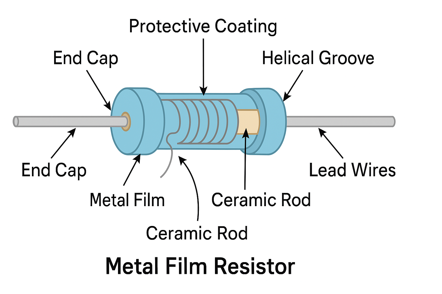
The structure of a metal film resistor is made up of several distinct layers and materials, each playing a critical role in its function and durability. Below is a breakdown of the typical construction elements:
1. Structure Metal Film Resistor: Ceramic Rod Core (Substrate)
At the heart of the resistor is a cylindrical ceramic rod, usually made from alumina (Al₂O₃). This material is chosen for its electrical insulation and excellent thermal conductivity. It acts as the foundation upon which the metal film is deposited.
2. Metal Film Layer
A thin, uniform metallic film is vacuum-deposited onto the surface of the ceramic rod. Common materials used for the film include:
- Nickel-chromium (NiCr)
- Tin oxide
- Gold-palladium alloys
This metal layer is the actual resistive element that impedes electrical current based on its thickness and length. The resistance value is determined by trimming or cutting a spiral groove into the metal film (discussed below).
3. Structure Metal Film Resistor: Helical Groove (Trimming Spiral)
To achieve the desired resistance value, a laser or abrasive cutting tool is used to create a helical (spiral) groove in the metal film. This increases the length of the resistive path and thereby adjusts the resistance.
This trimming process provides high precision (with tolerance levels as low as ±0.1%) and is one of the defining advantages of metal film resistors.
4. End Caps and Lead Wires
Each end of the resistor has metal end caps—typically made of silver or nickel-plated brass—that connect to the resistive film. From these caps, lead wires (usually made of tin-plated copper) are attached for mounting on a circuit board.
These wires are often straight (axial) and are soldered into place during circuit assembly.
5. Structure Metal Film Resistor: Protective Coatings
To protect the resistive element from environmental damage, oxidation, and mechanical stress, several layers of protective coatings are applied:
- Inner Coating: Typically epoxy resin, this provides electrical insulation and mechanical strength.
- Outer Coating: Often a colored lacquer or enamel with coding bands indicating resistance value (via the resistor color code).
Multiple layers of lacquer may be added to improve moisture resistance and insulation resistance.
6. Color Code Bands
The external surface of the resistor is marked with color-coded bands that represent:
- Resistance value (in ohms)
- Tolerance (precision)
- Temperature coefficient (optional)
This coding allows for quick identification during manufacturing and circuit design.
Manufacturing Process of Metal Film Resistors
The steps involved in producing a metal film resistor include:
- Preparing the Ceramic Rod: The substrate is cleaned and prepared for metal deposition.
- Vacuum Deposition: A metal layer is uniformly deposited onto the rod using sputtering or evaporation techniques.
- Trimming the Resistance: Precision laser tools cut the spiral groove to set the resistance value.
- Applying End Caps and Leads: Metal caps are affixed, and wires are soldered or mechanically crimped.
- Coating and Marking: Protective lacquer coatings are applied, and color code bands are painted.
- Testing and Quality Control: Finished resistors undergo rigorous testing to ensure tolerance, temperature coefficient, and resistance value meet specifications.
Advantages of Metal Film Resistors
The structure of metal film resistors gives them several benefits:
- High Precision: Tolerances as tight as ±0.1% are possible.
- Temperature Stability: Low temperature coefficient of resistance (TCR), typically ±50 ppm/°C.
- Low Noise: Metal film resistors produce minimal thermal and electrical noise compared to carbon resistors.
- Durability: Excellent performance in high-humidity and high-temperature environments.
- Long-Term Stability: Resistance values remain stable over time with minimal drift.
Applications of Metal Film Resistors
Thanks to their stable structure and performance, metal film resistors are widely used in:
- Precision analog circuits
- Audio equipment
- Medical instruments
- Measuring and test equipment
- Communication devices
- Industrial automation controls
Their use is preferred wherever low tolerance, low noise, and reliability are vital.
Limitations to Consider
Despite their advantages, metal film resistors are not ideal for every scenario:
- Cost: They are more expensive than carbon film resistors.
- Power Handling: Typically limited to 0.25W to 2W, not ideal for high-power circuits.
- Fragility: The ceramic body and thin metal layer can be damaged under mechanical stress or overvoltage conditions.

Structure Metal Film Resistor vs. Other Resistor Types
To understand the advantages of the metal film structure, it helps to compare with other resistor types:
| Feature | Metal Film | Carbon Film | Wirewound |
|---|---|---|---|
| Precision | High (±0.1–1%) | Medium (±2–5%) | Very High (±0.01–1%) |
| Temperature Stability | Excellent | Moderate | Excellent |
| Noise | Very Low | High | Very Low |
| Power Handling | Moderate | Moderate | High |
| Cost | Moderate | Low | High |
Conclusion of Structure Metal Film Resistor
The structure of metal film resistors plays a critical role in their performance, reliability, and widespread use in precision electronic applications. From the ceramic substrate to the metal film layer, spiral trimming, and protective coatings, each component contributes to their superior electrical characteristics.
For designers and engineers aiming for stable, noise-free, and accurate resistance values, metal film resistors are an excellent choice. Understanding their internal structure enables better selection and application in today’s increasingly complex electronic systems.
Call to Action
Need more insights into electronic components? Visit Abi Royen – https://abiroyen.com for detailed guides, tutorials, and expert content in the world of electronics and embedded systems.