

Introduction of Limitations of Thyristors
Limitations of Thyristors ~ Thyristors, also known as Silicon Controlled Rectifiers (SCRs), are widely used in power electronics applications such as controlled rectifiers, inverters, AC voltage regulators, and motor drives. Their ability to handle high voltages and large currents makes them indispensable in high-power industrial systems.
However, like any semiconductor device, thyristors come with inherent limitations that restrict their application in certain areas. Despite their advantages, issues such as switching characteristics, control complexity, and commutation requirements prevent thyristors from being the universal solution in power electronics.
This article provides a comprehensive discussion of the limitations of thyristors, their impact on design, and the scenarios where alternative devices like transistors, IGBTs, or MOSFETs are preferred.
1. Basic Characteristics of Thyristors
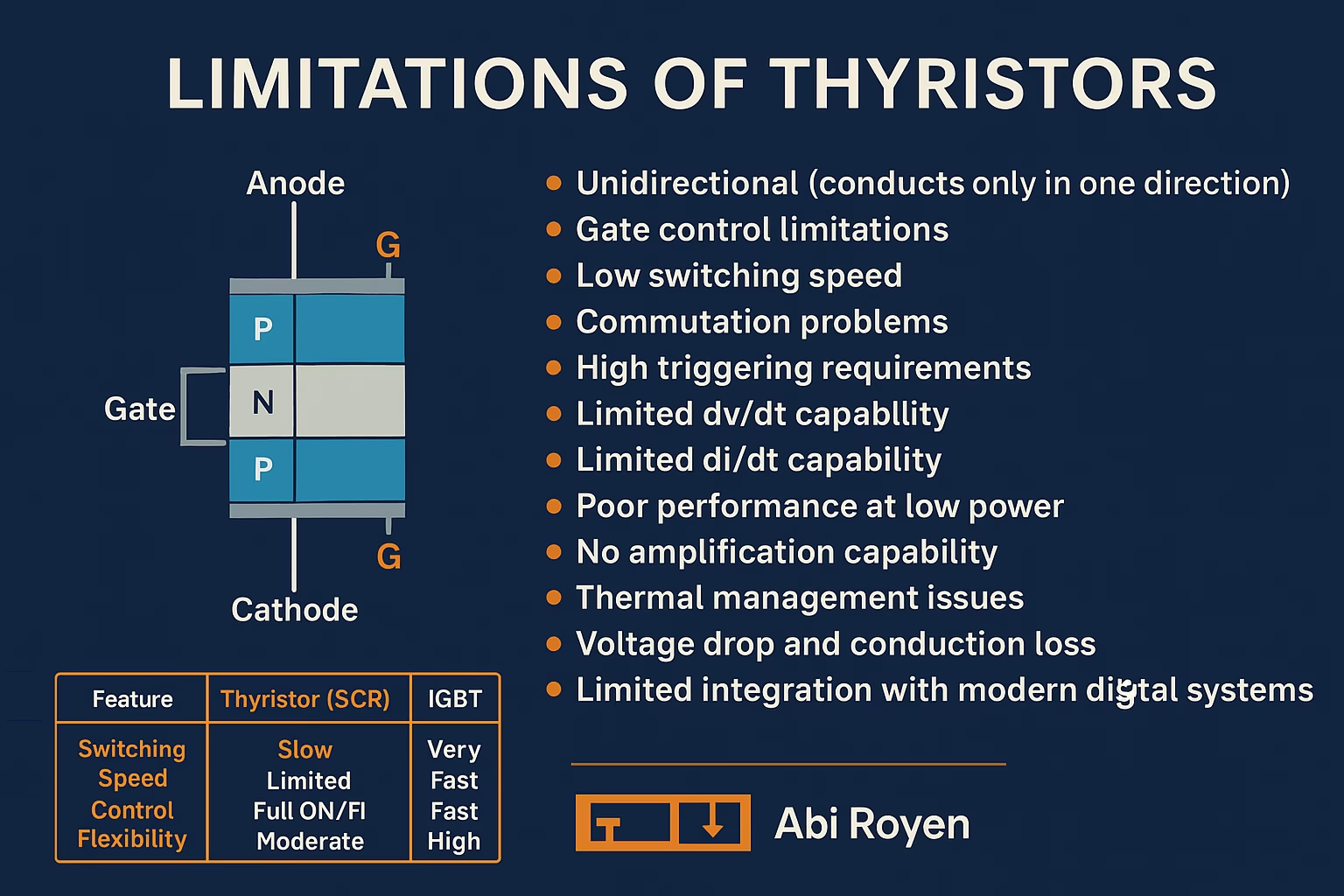
Before exploring their drawbacks, it is essential to understand what makes thyristors unique. A thyristor is a four-layer PNPN semiconductor device with three junctions and three terminals:
- Anode (A) – Positive terminal
- Cathode (K) – Negative terminal
- Gate (G) – Trigger input
Thyristors remain in the OFF state until a triggering pulse is applied to the gate. Once turned ON, they remain conducting until the current falls below a certain holding level.
This latching behavior is both an advantage (in high-power applications) and a limitation (in fast switching and low-power electronics).
2. Major Limitations of Thyristors
2.1 Limitations of Thyristors: Unidirectional Nature
Thyristors are inherently unidirectional devices—they conduct current only in one direction (from anode to cathode). This restricts their use in AC applications where bidirectional control is needed. To overcome this, additional circuitry such as TRIACs or dual thyristor configurations must be used.
Impact: More complex design and higher costs in AC power control.
2.2 Gate Control Limitations
Unlike transistors, where the gate (or base) signal continuously controls conduction, thyristors require only a single gate pulse to turn ON. After latching, they cannot be turned OFF by the gate.
Drawback:
- Lack of full control over switching
- Requires external commutation circuits for forced turn-OFF in DC applications
This makes them less flexible compared to MOSFETs or IGBTs, which allow gate-controlled ON and OFF switching.
2.3 Limitations of Thyristors: Low Switching Speed
Thyristors suffer from slow turn-ON and turn-OFF times. The typical switching time is much longer than that of MOSFETs or IGBTs.
Limitations include:
- Unsuitable for high-frequency applications (e.g., RF electronics, fast switching power supplies)
- Increased power losses due to slow switching
- Limitation in compact, high-efficiency power circuits
2.4 Commutation Problems
Once turned ON, a thyristor will only switch OFF when:
- The current through it drops below the holding current, or
- An external commutation circuit forces it OFF.
In AC applications, natural commutation occurs every half cycle. But in DC applications, special forced commutation circuits are needed, making the system more complex.
2.5 Limitations of Thyristors: High Triggering Requirements
For reliable operation, thyristors need a minimum gate current and voltage. If the gate triggering signal is too weak, the device may fail to switch ON properly, leading to misfiring or partial conduction.
This increases circuit complexity in sensitive electronic systems.
2.6 Limited dv/dt Capability
Thyristors are highly sensitive to the rate of rise of voltage (dv/dt). A fast voltage change across the terminals can cause false triggering, leading to unintentional turn-ON without a gate signal.
To prevent this, designers must add snubber circuits, which increase cost and design complexity.
2.7 Limitations of Thyristors: Limited di/dt Capability
When turned ON, the current through a thyristor should rise gradually. A high rate of current increase (di/dt) can damage the device due to localized hot spots.
Thus, series inductors are often required to limit di/dt, further complicating the circuit design.
2.8 Poor Performance at Low Power
Thyristors are most effective in high-power applications. In low-power circuits, their drawbacks (such as large gate current requirements and lack of easy turn-OFF) outweigh their benefits.
For example:
- In low-power switching circuits, MOSFETs or BJTs are preferred.
- Thyristors are rarely used in small consumer electronics.
2.9 No Amplification Capability
Unlike transistors, thyristors cannot amplify signals. They act purely as switches, either fully ON or fully OFF.
This restricts their applications to power control only, not in signal processing or amplification tasks.
2.10 Thermal Management Issues
Thyristors handle large currents and voltages, which generate significant heat. They require heatsinks, cooling systems, or thermal management solutions to prevent overheating.
This adds bulk and cost, especially in compact electronic systems.
2.11 Limitations of Thyristors: Voltage Drop and Conduction Loss
Even when ON, thyristors have a forward voltage drop (typically around 1–2V), which leads to power losses in high-current systems. Over time, this reduces system efficiency compared to more advanced semiconductor devices.
2.12 Limited Integration with Modern Digital Systems
Thyristors are less compatible with modern microprocessor-controlled circuits that require fast, precise, and reversible switching. Their slow response and lack of turn-OFF control limit their use in digital power management systems.

3. Comparison with Alternative Devices
| Feature | Thyristor (SCR) | MOSFET | IGBT | BJT |
|---|---|---|---|---|
| Switching Speed | Slow | Very Fast | Fast | Moderate |
| Control Flexibility | Limited | Full ON/OFF control | Full control | Full control |
| Frequency Capability | Low | Very High | Moderate-High | Moderate |
| Power Handling | Very High | Moderate | High | Low-Moderate |
| Gate/Base Drive | Pulse only (ON) | Continuous control | Continuous | Continuous |
| Turn-OFF Control | External circuit needed | Easy | Easy | Easy |
This comparison shows why MOSFETs and IGBTs are often chosen in modern power electronic designs where speed, efficiency, and control flexibility are critical.
4. Applications Despite Limitations
Even with these drawbacks, thyristors remain valuable in specific applications where high-power handling outweighs their limitations:
- AC power control – Light dimmers, fan regulators
- Motor drives – Industrial speed controllers
- HVDC transmission systems – High-voltage rectification
- Power converters – Controlled rectifiers and inverters
- Over-voltage protection – Crowbar circuits
5. Future Trends: Overcoming Limitations
Research and innovation aim to overcome traditional thyristor drawbacks. Some modern advancements include:
- GTO (Gate Turn-Off Thyristors): Allow turning OFF using gate signals, solving commutation issues.
- IGCT (Integrated Gate-Commutated Thyristors): Improved speed and control.
- Light-Triggered Thyristors (LTTs): Use optical control for better isolation and precision.
These innovations extend the relevance of thyristors in modern power systems while addressing their limitations.
Conclusion of Limitations of Thyristors
Thyristors are powerful semiconductor devices, capable of handling extreme voltages and currents in industrial and power transmission systems. However, their limitations—such as slow switching, lack of gate-controlled turn-OFF, commutation difficulties, and poor high-frequency performance—restrict their use in modern, fast-switching, and low-power applications.
For applications requiring precision, high frequency, or digital integration, alternatives like MOSFETs and IGBTs are preferred. Still, in heavy-duty industrial applications, thyristors remain indispensable.
By understanding these limitations, engineers can make informed choices about when to use thyristors and when to choose alternative semiconductor devices.