

Operational amplifiers, commonly known as Op-Amps, are among the most versatile and widely used components in modern electronics. They serve as the foundation for countless analog circuit designs ranging from audio systems to instrumentation and control systems. To fully leverage their potential, engineers must understand the basic operational amplifier configurations, as each configuration serves unique purposes and applications.
This article provides an in-depth exploration of the fundamental Op-Amp configurations, their principles of operation, and practical applications.
1. Introduction to Operational Amplifiers
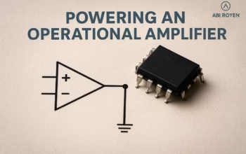
An operational amplifier is a high-gain differential amplifier with two input terminals:
- Inverting input (−)
- Non-inverting input (+)
It produces an output voltage proportional to the difference between these inputs, multiplied by the open-loop gain of the amplifier.
Key features of an ideal Op-Amp include:
- Infinite input impedance (no current flows into the inputs)
- Zero output impedance (ideal for driving loads)
- Infinite open-loop gain
- Infinite bandwidth
Although practical Op-Amps have limitations, they are designed to approximate these characteristics as closely as possible.
2. Importance of Basic Operational Amplifier Configurations
While Op-Amps can be used in countless ways, there are a few basic configurations that serve as building blocks for more complex circuits. These configurations allow engineers to:
- Control signal amplification
- Perform mathematical operations such as addition, subtraction, integration, and differentiation
- Filter and shape signals
- Build comparators and oscillators
Mastering these basic configurations is crucial for anyone studying or working in electronics.

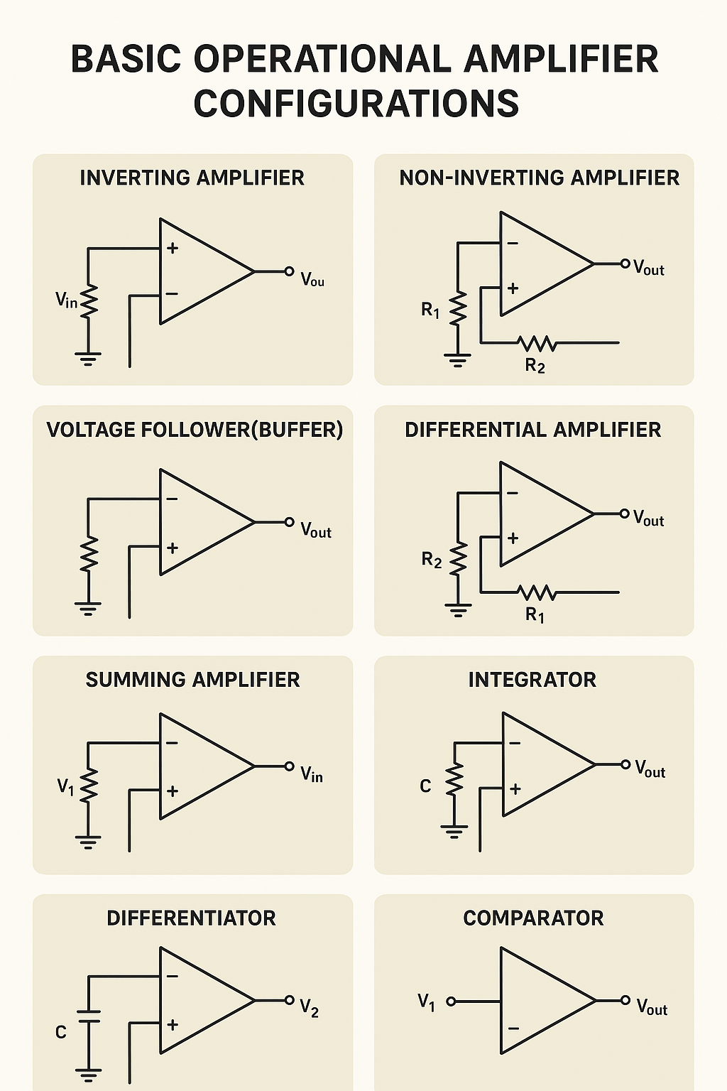
3. Basic Operational Amplifier Configurations
3.1 Inverting Amplifier
The inverting amplifier configuration is one of the simplest and most important.
- Principle: The input signal is applied to the inverting terminal through a resistor, while the non-inverting terminal is connected to ground. A feedback resistor is placed between the output and the inverting input.
- Voltage Gain Formula:
Av=−RfRinA_v = -\frac{R_f}{R_{in}}Av=−RinRf
Here, RfR_fRf is the feedback resistor, and RinR_{in}Rin is the input resistor. The negative sign indicates a 180° phase shift between input and output.
- Applications:
- Audio amplification
- Signal inversion
- Analog computing circuits
3.2 Non-Inverting Amplifier
The non-inverting amplifier configuration provides amplification without phase inversion.
- Principle: The input signal is applied to the non-inverting terminal. A resistor divider network connects the output back to the inverting input.
- Voltage Gain Formula:
Av=1+RfRinA_v = 1 + \frac{R_f}{R_{in}}Av=1+RinRf
- Advantages:
- High input impedance
- Output in phase with input
- Applications:
- Buffer stages
- Sensor signal conditioning
- Measurement systems
3.3 Voltage Follower (Buffer)
Also known as a unity-gain amplifier, this configuration is a special case of the non-inverting amplifier.
- Principle: The output is directly connected to the inverting input, creating a closed loop with unity gain.
- Characteristics:
- Gain = 1
- Very high input impedance
- Very low output impedance
- Applications:
- Signal isolation
- Driving low-impedance loads
- Preventing loading effects in measurement systems
3.4 Differential Amplifier
The differential amplifier amplifies the difference between two input signals.
- Principle: By applying two signals to both the inverting and non-inverting terminals, the circuit produces an output that reflects their voltage difference.
- Voltage Gain Formula:
Vout=RfRin(V2−V1)V_{out} = \frac{R_f}{R_{in}} (V_2 – V_1)Vout=RinRf(V2−V1)
- Applications:
- Noise rejection in sensor systems
- Balanced audio circuits
- Building blocks of instrumentation amplifiers
3.5 Summing Amplifier
The summing amplifier configuration allows multiple input signals to be added together.
- Principle: Several input resistors feed different signals into the inverting input, while the feedback resistor controls the overall gain.
- Formula:
Vout=−Rf(V1R1+V2R2+…)V_{out} = -R_f \left( \frac{V_1}{R_1} + \frac{V_2}{R_2} + … \right)Vout=−Rf(R1V1+R2V2+…)
- Applications:
- Audio mixers
- Weighted signal combination
- Analog computing
3.6 Integrator
The integrator configuration performs mathematical integration of the input signal over time.
- Principle: A capacitor is used in place of the feedback resistor, and the output voltage represents the integral of the input.
- Formula:
Vout=−1RC∫Vin dtV_{out} = -\frac{1}{RC} \int V_{in} \, dtVout=−RC1∫Vindt
- Applications:
- Waveform generation (triangular/sawtooth waves)
- Analog computers
- Signal processing
3.7 Differentiator
The differentiator configuration performs mathematical differentiation of the input signal.
- Principle: A capacitor is placed at the input, and a resistor is used in the feedback path.
- Formula:
Vout=−RCdVindtV_{out} = -RC \frac{dV_{in}}{dt}Vout=−RCdtdVin
- Applications:
- Edge detection in signals
- High-pass filtering
- Wave-shaping circuits
3.8 Comparator
Although not a linear configuration, the comparator is one of the most common Op-Amp applications.
- Principle: The Op-Amp compares two input voltages and outputs either a high or low voltage depending on which input is greater.
- Applications:
- Zero-crossing detectors
- Voltage level detection
- Analog-to-digital conversion
4. Practical Considerations
When implementing Op-Amp circuits, engineers must consider real-world limitations:
- Input bias currents
- Finite open-loop gain
- Slew rate limitations
- Bandwidth constraints
- Power supply requirements
Using proper design practices ensures accurate and stable performance.
5. Applications of Basic Operational Amplifier Configurations
Op-Amps play a crucial role in:
- Consumer electronics (audio amplifiers, mixers, filters)
- Instrumentation (sensors, data acquisition, signal conditioning)
- Industrial automation (control systems, measurement circuits)
- Communication systems (modulators, demodulators, filters)
- Power electronics (PWM controllers, analog control loops)
Their versatility makes them indispensable in nearly every field of electronics.
6. Conclusion of Basic Operational Amplifier Configurations
Understanding the basic operational amplifier configurations is essential for mastering analog circuit design. From simple inverting and non-inverting amplifiers to more advanced integrators, differentiators, and comparators, Op-Amps provide the foundation for countless applications.
For students, hobbyists, and professionals alike, Op-Amps remain one of the most powerful tools in the electronics toolbox. By mastering these configurations, you gain the ability to design, analyze, and innovate across a wide range of electronic systems.