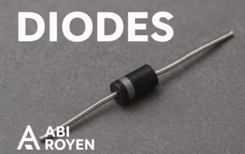

Introduction of Test a Diode
Test a Diode ~ Diodes are among the most essential components in electronics. They act as one-way valves for electrical current, allowing current to flow in one direction while blocking it in the opposite. Because of their critical role in rectifiers, power supplies, signal circuits, and protection devices, ensuring a diode is functioning correctly is vital.
Testing a diode may seem intimidating for beginners, but with the right tools and knowledge, the process is straightforward. In this guide, we will cover everything you need to know about how to test a diode, including preparation, testing methods, troubleshooting, and common errors to avoid.
What is a Diode?
Before jumping into testing, let’s quickly revisit what a diode is.
- Basic Definition: A diode is a semiconductor device that allows current to flow only in one direction (from anode to cathode).
- Symbol: The diode symbol shows a triangle pointing towards a line. The triangle represents the anode, and the line represents the cathode.
- Function: Diodes are commonly used for rectification, voltage regulation, signal demodulation, and circuit protection.
Knowing how a diode works helps you understand what you’re measuring when testing.
Why Test a Diode?
There are several reasons you may need to test a diode:
- Circuit Troubleshooting – When diagnosing faulty circuits, a bad diode could be the cause.
- Component Verification – Before installing a diode in a new project, it’s best to check if it works.
- Preventive Maintenance – In industrial electronics, testing diodes can prevent costly downtime.
Tools Required for Test a Diode
To test a diode effectively, you’ll need:
- Digital Multimeter (DMM): The most common tool for diode testing, featuring a dedicated “diode test mode.”
- Analog Multimeter (Optional): Useful for cross-verification but less precise.
- Circuit Diagram (Optional): Helps in identifying diode placement if testing within a circuit.
Methods of Test a Diode
There are several methods available depending on the tools you have. Let’s break them down.
1. Using a Digital Multimeter (Preferred Method)
Most modern digital multimeters have a diode test mode. This is the easiest and most reliable method.
Steps:
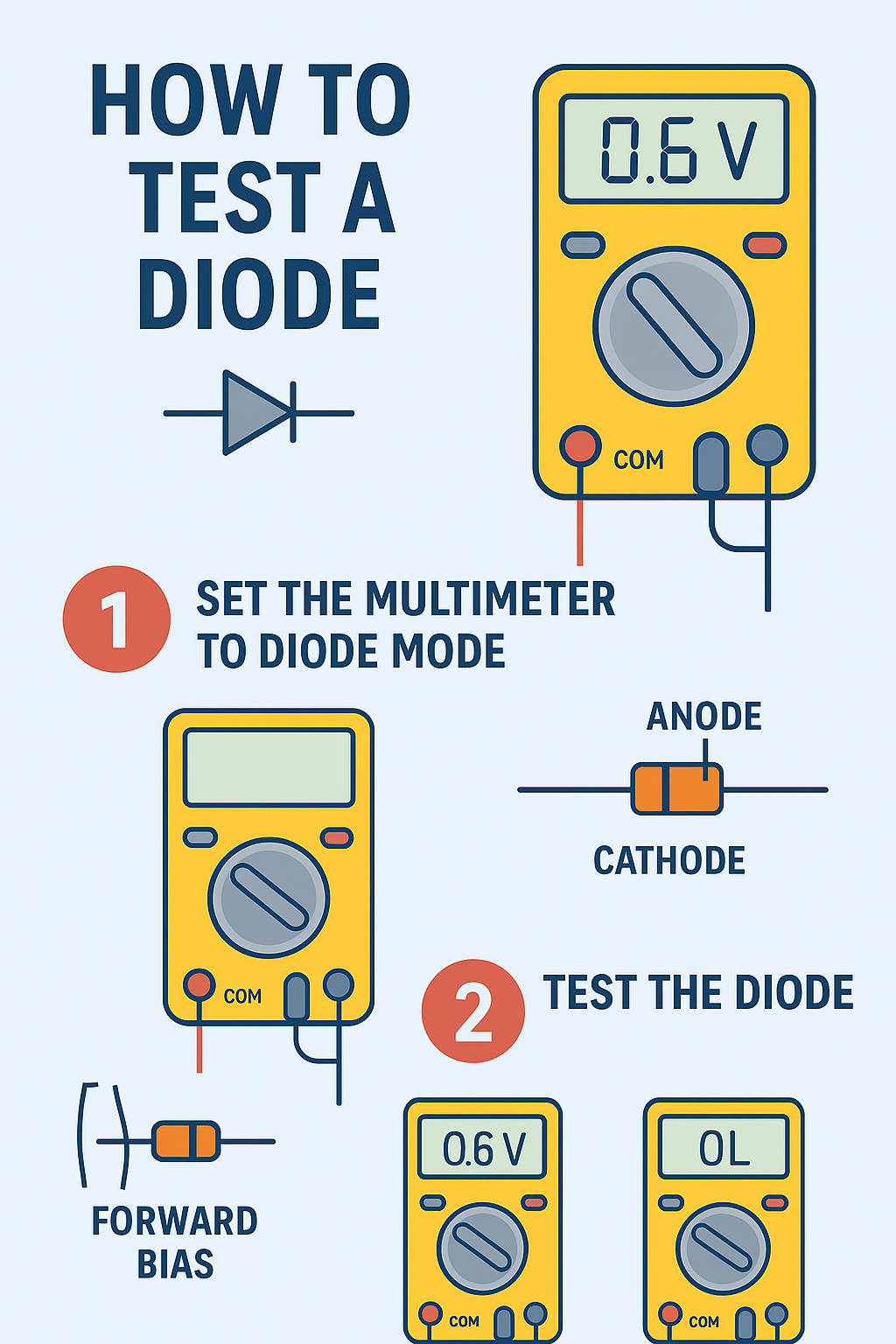
- Turn the multimeter dial to diode mode (symbol resembles a diode).
- Identify diode terminals: The anode (+) and cathode (–). The cathode often has a stripe marking.
- Forward Bias Test:
- Connect the red probe to the anode and the black probe to the cathode.
- A healthy diode should display a voltage drop between 0.6V to 0.7V (for silicon diodes) or around 0.2V to 0.3V (for germanium diodes).
- Reverse Bias Test:
- Reverse the probes (red to cathode, black to anode).
- The multimeter should show OL (over-limit) or no conduction, meaning the diode blocks reverse current.
Interpretation:
- Good Diode: Forward bias shows ~0.6–0.7V, reverse bias shows OL.
- Shorted Diode: Shows 0V in both directions.
- Open Diode: Shows OL in both directions.
2. Using an Analog Multimeter
An analog multimeter works slightly differently.
Steps:
- Set the meter to the resistance (ohms) setting.
- Forward Bias Test:
- Red probe on cathode, black probe on anode (since analog meters supply voltage differently).
- The needle should deflect, showing low resistance.
- Reverse Bias Test:
- Swap probes.
- The needle should not move (infinite resistance).
Interpretation: Same as digital multimeter results.
3. Testing a Diode in a Circuit
Sometimes, diodes need to be tested without removing them from the circuit.
- Forward Bias: A working diode still shows the expected voltage drop.
- Reverse Bias: Should show high resistance or OL.
⚠ Note: Other components in parallel can affect readings. If uncertain, desolder one diode leg for accurate testing.
Common Test a Diode Mistakes
Even experienced technicians can make mistakes when testing diodes. Avoid these pitfalls:
- Wrong Multimeter Setting: Forgetting to select diode mode or ohms setting.
- Misidentifying Terminals: Confusing anode and cathode leads to misinterpretation.
- Testing in Circuit Without Consideration: Other paths may distort results.
- Ignoring Temperature Effects: High temperatures can lower forward voltage drop readings.
Troubleshooting Diode Issues
- If the diode reads short (0V both ways): It’s defective and must be replaced.
- If the diode reads open (OL both ways): It has failed and should be replaced.
- If readings are inconsistent: Retest after disconnecting one terminal from the circuit.
Advanced Test a Diode Techniques
For special diodes, different methods may be required:
- Zener Diodes: Require a voltage source higher than their breakdown voltage to test properly.
- LEDs (Light Emitting Diodes): Can be tested with a diode mode on a multimeter; they should glow faintly in forward bias.
- Schottky Diodes: Have a lower forward voltage drop (0.2–0.3V), so expect different readings.
Conclusion
Testing a diode is a fundamental skill in electronics. Whether you are a beginner learning circuits or a professional troubleshooting complex systems, knowing how to test a diode ensures reliability and prevents costly issues.
By following the step-by-step methods outlined—using a digital or analog multimeter—you can quickly determine if a diode is functioning correctly. Remember to always verify with both forward and reverse bias, and when in doubt, test outside the circuit.
Mastering this skill will not only improve your electronics knowledge but also save time and resources in your projects.