
Operational amplifiers, often called Op-Amps, are among the most widely used components in analog electronics. They serve as the backbone of countless circuits, from audio systems and instrumentation devices to filters and power regulation systems. To design or analyze circuits effectively, engineers must thoroughly understand operational amplifier parameters and specifications.
In this article, we will explore the key parameters of Op-Amps, why they matter, and how they impact real-world applications.
What is an Operational Amplifier?
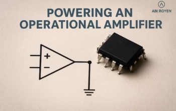
An operational amplifier is a high-gain electronic voltage amplifier with differential inputs and usually a single-ended output. It is commonly represented in circuit diagrams by a triangular symbol with two input terminals (inverting “–” and non-inverting “+”) and one output terminal.
In an ideal world, Op-Amps have infinite gain, infinite input impedance, and zero output impedance. However, in practice, physical limitations introduce non-ideal characteristics. These limitations are quantified through Op-Amp parameters and specifications.
Key Operational Amplifier Parameters
Let’s break down the most important Op-Amp parameters every electronics engineer should know:
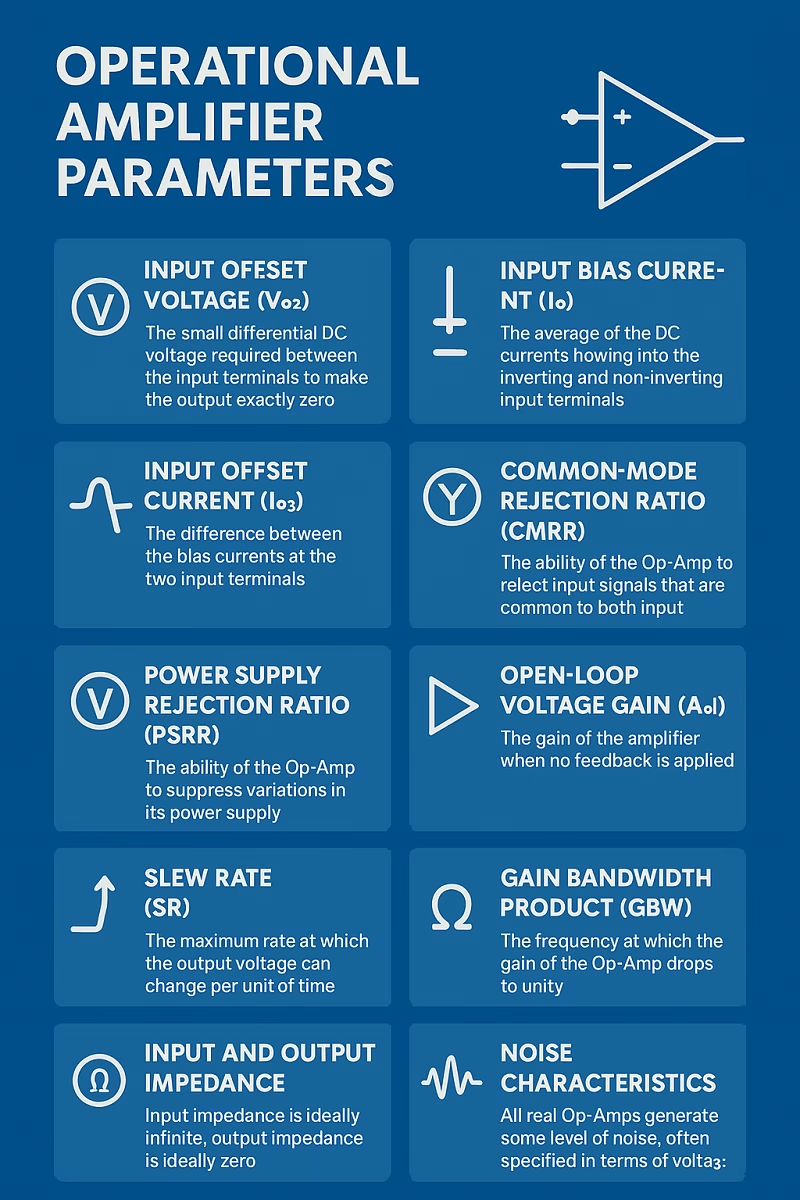
1. Operational Amplifier Parameters: Input Offset Voltage (Vos)
- Definition: The small differential DC voltage required between the input terminals to make the output exactly zero.
- Why it matters: In real circuits, input offset voltage can cause output errors, especially in high-gain configurations.
- Example: A 2 mV offset voltage amplified by a gain of 1000 could result in a 2 V output error.
2. Operational Amplifier Parameters: Input Bias Current (Ib)
- Definition: The average of the DC currents flowing into the inverting and non-inverting input terminals.
- Impact: These small currents (typically nanoamperes to microamperes) can create voltage drops across resistors, causing output inaccuracies.
- Consideration: Low bias current Op-Amps are essential for high-impedance sensor applications.
3. Input Offset Current (Ios)
- Definition: The difference between the bias currents at the two input terminals.
- Effect: It contributes to imbalance in differential inputs, creating further output errors.
4. Common-Mode Rejection Ratio (CMRR)
- Definition: The ability of the Op-Amp to reject input signals that are common to both input terminals.
- Expression: Typically expressed in decibels (dB).
- Importance: A high CMRR (e.g., 100 dB) ensures that noise or interference appearing equally on both inputs does not affect the output.
5. Power Supply Rejection Ratio (PSRR)
- Definition: The ability of an Op-Amp to suppress variations in its power supply voltage.
- Relevance: Low PSRR can lead to power line noise coupling into sensitive signals.
- Applications: Critical in precision measurement systems.
6. Operational Amplifier Parameters: Open-Loop Voltage Gain (Aol)
- Definition: The gain of the amplifier when no feedback is applied.
- Reality: Ideal Op-Amps have infinite gain, but real Op-Amps may have gains in the range of 100,000 or more.
- Impact: Higher gain improves accuracy in closed-loop configurations.
7. Operational Amplifier Parameters: Slew Rate (SR)
- Definition: The maximum rate at which the output voltage can change per unit of time (V/µs).
- Why it matters: Determines the Op-Amp’s ability to handle high-frequency signals.
- Example: If an Op-Amp has a slew rate of 0.5 V/µs, it cannot properly amplify signals requiring faster voltage changes.
8. Gain Bandwidth Product (GBW)
- Definition: The frequency at which the gain of the Op-Amp drops to unity (1).
- Effect: Determines the maximum frequency at which the Op-Amp can provide useful amplification.
- Example: An Op-Amp with 1 MHz GBW can provide a gain of 10 up to 100 kHz.
9. Input and Output Impedance
- Input Impedance: Ideally infinite, but practically in the range of megaohms or gigaohms. High input impedance ensures minimal loading of the source.
- Output Impedance: Ideally zero, but in practice, a few ohms. Low output impedance allows the Op-Amp to drive loads effectively.
10. Operational Amplifier Parameters: Noise Characteristics
- Definition: All real Op-Amps generate some level of noise, often specified in terms of voltage noise (nV/√Hz).
- Importance: In low-signal applications such as medical instrumentation or audio circuits, low-noise Op-Amps are essential.
Other Important Parameters
- Input Common-Mode Voltage Range (ICMR): Defines the voltage range over which the Op-Amp inputs can operate.
- Output Voltage Swing: The range between the maximum positive and negative output voltages. Rail-to-rail Op-Amps are designed to maximize this range.
- Thermal Drift: Parameters like offset voltage and bias current can vary with temperature, affecting precision.
Applications of Op-Amps Based on Parameters
Understanding Op-Amp parameters is not just theoretical—it directly impacts design decisions:
- Audio Amplifiers: Slew rate and noise level are crucial for sound quality.
- Sensor Interfaces: Low bias current and high input impedance prevent signal distortion.
- Medical Devices: Low noise and high CMRR ensure accurate biosignal detection.
- Power Systems: High PSRR ensures stable operation despite supply fluctuations.
- High-Speed Circuits: A high GBW product and fast slew rate are mandatory.
How to Choose the Right Op-Amp
When selecting an operational amplifier, consider:
- Required accuracy (offset voltage, CMRR, PSRR).
- Required frequency response (GBW, slew rate).
- Load-driving capability (output current and impedance).
- Power consumption (important for battery-powered devices).
- Environmental factors (temperature stability and thermal drift).
Conclusion
Operational amplifiers are indispensable in electronics, but their effectiveness depends heavily on their parameters. By understanding concepts like offset voltage, bias current, CMRR, PSRR, slew rate, and gain bandwidth product, engineers can design circuits that are both precise and reliable.
Whether you are working on audio systems, instrumentation, or industrial electronics, mastering these Op-Amp parameters is a key step toward successful design.