
Introduction of Internal Structure Op-Amp
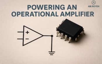
Internal Structure Op-Amp ~ Operational amplifiers, widely known as Op-Amps, are among the most essential components in analog electronics. They are used in applications ranging from signal conditioning and filtering to mathematical operations such as addition, subtraction, and integration.
While many students and engineers are familiar with the symbol and external characteristics of Op-Amps, a deeper understanding requires looking into their internal structure. The internal circuit reveals how multiple transistors, resistors, and other components are interconnected to deliver the powerful functionality of an Op-Amp.
This article explores the internal structure of an Op-Amp, breaking it into its fundamental stages: differential amplifier, gain stages, level shifter, and output stage. By the end, you will have a clear picture of how these stages work together to create one of the most versatile devices in electronics.
Overview of an Op-Amp
Before diving into the internal construction, let’s briefly review what an Op-Amp is.
- Definition: An operational amplifier is a high-gain direct current (DC) coupled electronic voltage amplifier with a differential input and a single-ended output.
- Inputs: It has two inputs, one inverting (-) and one non-inverting (+).
- Output: The output is the amplified difference between the two input voltages.
- Ideal vs Real: In theory, an Op-Amp has infinite gain, infinite input impedance, and zero output impedance. In reality, these parameters are finite but designed to be close to the ideal values.
To achieve these near-ideal characteristics, the Op-Amp is internally built using several stages of amplification and signal conditioning.
Block Diagram of Internal Structure Op-Amp
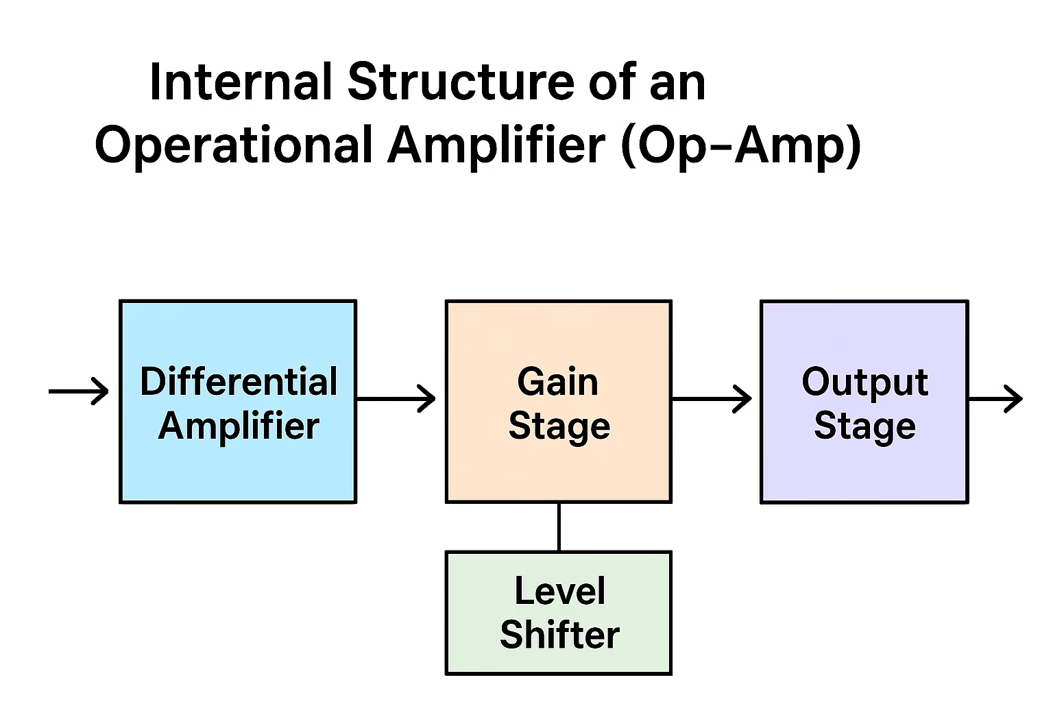
The internal structure of an Op-Amp can be represented by four main blocks:
- Input Stage (Differential Amplifier)
- Intermediate Stage (Gain Stage)
- Level Shifter (Voltage Level Translation)
- Output Stage (Buffering and Driving Capability)
Each stage has a specific role, and together they form a complete operational amplifier.
1. Differential Amplifier (Input Stage)
The differential amplifier is the heart of the Op-Amp. It takes two input voltages—one at the inverting terminal (-) and the other at the non-inverting terminal (+)—and amplifies the difference between them.
- Main Purpose:
- Provides high input impedance.
- Rejects common-mode signals (common-mode rejection ratio or CMRR).
- Amplifies only the difference between the input signals.
- Construction:
A typical differential amplifier is made using a pair of transistors (BJT or MOSFET) with their emitters (or sources) connected together through a constant current source. - Why it is Important:
This stage ensures that the Op-Amp responds only to the voltage difference between the two inputs, making it ideal for use in analog circuits like amplifiers, filters, and instrumentation systems.
2. Intermediate Gain Stage
Once the differential amplifier produces the initial output, it must be further amplified. That’s where the gain stage comes in.
- Main Purpose:
- Provides a very high voltage gain.
- Enhances the small differential signal to a level that can be processed by later stages.
- Construction:
- Often implemented as a common-emitter amplifier with active load.
- Uses current mirrors to ensure a stable biasing condition.
- Role in Performance:
This stage is crucial in achieving the open-loop gain of the Op-Amp, which can range from 10⁴ to 10⁶ in practical devices.
3. Level Shifter (DC Level Translation)
The gain stage output typically has a DC offset due to the transistor arrangement. To make the final output usable, this offset must be corrected. This is where the level shifter is introduced.
- Main Purpose:
- Removes unwanted DC voltage from the signal.
- Adjusts the signal to the correct level for the output stage.
- Construction:
- Usually implemented using a simple emitter follower (BJT) or a source follower (MOSFET).
- Provides no significant gain but ensures the signal is properly shifted.
- Impact:
Without the level shifter, the Op-Amp output would be DC-biased, which would limit its usability in AC signal amplification and other applications.
4. Output Stage
The final stage of the Op-Amp is the output stage, which provides the necessary current to drive external loads.
- Main Purpose:
- Reduces output impedance.
- Increases current-driving capability.
- Ensures stable and distortion-free output.
- Construction:
- Implemented as a push-pull amplifier (Class AB configuration).
- Provides both sourcing and sinking current.
- Performance Advantage:
The output stage ensures that the Op-Amp can drive low-resistance loads and deliver a strong, usable signal to the next stage in the circuit.
Complete Working of Internal Structure
When combined, the operation can be summarized as follows:
- The differential amplifier amplifies the voltage difference between input terminals.
- The gain stage boosts this signal to a high amplitude.
- The level shifter removes unwanted DC bias and adjusts the voltage level.
- The output stage strengthens the signal and provides the ability to drive loads.
This sequence allows the Op-Amp to function as a versatile amplifier with high gain, stability, and reliability.
Practical Example: µA741 Op-Amp
One of the most widely used Op-Amps, the µA741, demonstrates this internal structure.
- The input stage is built with a dual differential amplifier.
- The intermediate stage is a high-gain common-emitter amplifier.
- A level shifting circuit eliminates DC offset.
- The push-pull output stage delivers a stable output.
By studying the internal schematic of the µA741, students and engineers gain valuable insight into how these blocks are interconnected to produce a high-performance Op-Amp.
Importance of Understanding Internal Structure
Understanding the internal structure of Op-Amps is not only valuable for academic purposes but also practical design:
- Helps in troubleshooting circuit issues.
- Allows better selection of Op-Amps for specific applications.
- Enhances understanding of limitations such as input bias current, offset voltage, and slew rate.
- Aids in advanced analog design and customization.
Conclusion of Internal Structure Op-Amp
The internal structure of an Op-Amp is a carefully designed combination of stages that transform a tiny differential input into a powerful, stable output.
- The differential amplifier ensures high input impedance and CMRR.
- The gain stage boosts the voltage.
- The level shifter corrects DC levels.
- The output stage ensures proper load driving.
Together, these stages make the Op-Amp a versatile building block in electronics, widely used in amplifiers, filters, oscillators, and countless other applications.
By understanding the internal construction, engineers and students gain a deeper appreciation of how Op-Amps achieve their remarkable performance.