
Introduction of Working Principle of Thyristors
In the world of power electronics, thyristors are among the most essential semiconductor devices. They play a crucial role in controlling high voltages and currents in various electrical and industrial applications. Understanding the working principle of thyristors is fundamental for engineers, technicians, and students dealing with electronic circuits, power supplies, and motor control systems.
This article will explore the detailed structure, operation, triggering methods, and applications of thyristors, helping readers gain a clear understanding of how this device functions in real-world systems.
What is a Thyristor?
A thyristor is a four-layer, three-junction semiconductor device that acts as a switch, allowing current to flow when triggered and continuing to conduct until the current drops below a certain threshold. The most common type of thyristor is the Silicon Controlled Rectifier (SCR).
Basic Characteristics of Thyristors:
- Made of alternating P-type and N-type semiconductor layers.
- Has three terminals:
- Anode (A) – positive terminal.
- Cathode (K) – negative terminal.
- Gate (G) – control terminal.
- Works as a unidirectional device, allowing current to flow in one direction only.
Structure of a Thyristor
The thyristor consists of four semiconductor layers (PNPN) forming three junctions: J1, J2, and J3.
- J1 and J3 are forward-biased when the anode is positive with respect to the cathode.
- J2 remains reverse-biased until a triggering signal is applied at the gate.
This layered structure gives the thyristor its unique switching properties.
Working Principle of Thyristors
The working principle of a thyristor is based on latching and triggering mechanisms. It behaves like a switch that remains OFF until triggered, and once it turns ON, it stays conducting until the current naturally goes to zero or is forcibly interrupted.
1. Forward Blocking Mode (OFF State)
- When the anode is positive with respect to the cathode and no gate current is applied, junction J2 is reverse-biased.
- This prevents the flow of current.
- The thyristor remains in the blocking state.
2. Forward Conduction Mode (ON State)
- If a small current is applied to the gate terminal, it activates the device.
- Junction J2 breaks down, allowing a large current to flow from anode to cathode.
- Once triggered, the thyristor remains in the ON state even if the gate current is removed.
3. Reverse Blocking Mode
- When the cathode is made positive with respect to the anode, junctions J1 and J3 are reverse-biased.
- The thyristor blocks current just like a diode in reverse bias.
Two-Transistor Model of Thyristor
The working principle can also be explained using the two-transistor analogy:
- The thyristor can be considered as a combination of one PNP transistor and one NPN transistor connected in feedback mode.
- A small gate current triggers one transistor, which in turn activates the other, creating a regenerative action that latches the device ON.
Triggering Methods of Thyristors
To turn ON a thyristor, different triggering techniques are used:
- Gate Triggering – Applying a positive pulse at the gate terminal.
- Forward Voltage Triggering – Increasing forward voltage until breakdown occurs.
- dv/dt Triggering – A rapid rate of voltage change across the device.
- Temperature Triggering – Excessive heating reduces the barrier at J2, turning the device ON.
- Light Triggering (LASCR) – A light-activated SCR uses photons to initiate conduction.
Among these, gate triggering is the most common and widely used method in industrial applications.
Turn-Off Mechanism
Unlike a transistor, a thyristor cannot be simply turned off by removing the gate signal. It requires:
- Natural Commutation (Line Commutation) – In AC circuits, when current passes through zero, the device turns off naturally.
- Forced Commutation – In DC circuits, external circuits are required to bring the current to zero and turn off the device.

Advantages of Thyristors
- Can handle high voltage and current.
- Efficient switching with minimal power loss.
- Compact and reliable semiconductor device.
- Widely available and cost-effective.
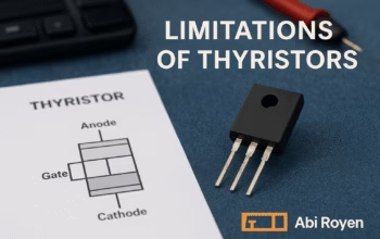
Limitations of Thyristors
- Unidirectional operation (cannot conduct in reverse direction).
- Requires external commutation in DC circuits.
- Slower switching compared to modern devices like IGBTs or MOSFETs.
Applications of Thyristors
Thyristors are extensively used in power control and conversion systems. Some common applications include:
- AC Power Control – For controlling lamps, heaters, and motor speeds.
- Motor Drives – Used in DC and AC motor control.
- Rectifiers – Controlled rectification in power supplies.
- Inverters & Converters – Converting AC to DC and vice versa.
- Voltage Regulators – Stabilizing power in industrial equipment.
- Overvoltage Protection – Crowbar circuits use thyristors to protect sensitive equipment.
Future of Thyristors
Although newer semiconductor devices like IGBTs and MOSFETs are gaining popularity, thyristors remain relevant due to their ruggedness, reliability, and ability to handle very high power levels. They are still the preferred choice in HVDC transmission systems, induction heating, and power grid control.
Conclusion of Working Principle of Thyristors
The working principle of thyristors is based on their ability to switch ON using a triggering signal and remain latched until the current naturally ceases. Their simple structure, robustness, and efficiency make them essential in high-power applications.
Understanding thyristors not only helps in designing effective power control systems but also lays the foundation for learning advanced semiconductor devices.
For engineers, students, and professionals, mastering thyristor operation is a key step toward exploring the vast field of power electronics.